JeonLab AVR/ESP programmer

Integrated (ISP & FTDI) programmer for AVR and ESP

For my projects, I have used a few different micro-controllers such as ATmega328p, ATtiny85v, ESP-01, and ESP32. In order to flash (programs or boot loaders) the micro-controllers, you need programmers. There are commercial products you can buy, but there are cheaper way to do the same.

There are two ways I usually use to flash the chips: 1) UART (using serial ports of the chip through serial to USB converter, FTDI for example); and 2) Arduino ISP (In-System-Programmer, using SPI (Serial Peripheral Interface) protocol).

I have made a programmer for the ATtiny85/ATtiny45 chips (see this post), and another one for ESP-01 (see this post). But for the other chips like ATmega328p DIP package, I usually program them with another Arduino board (Jeonlab mini v1.3 for example) and an FTDI break-out on a breadboard. For the ATmega328p TQFP package, I have used the Arduino as ISP method through SPI bus.

The ESP chips have pre-loaded firmware with a boot-loader, so I only need the FTDI breakout board with the RTS pin enabled.

Recently, I started thinking to integrate all these into a single board that consists of:

  • FT232RL chip for FTDI
  • ATmega328p TQFP with Arduino as ISP program loaded
  • 5V to 3.3V regulator (600mA max.) for 3.3V output (FTDI has 3.3V output but 50mA max.)
  • FTDI IO voltage selector (5V or 3V3)
  • V-out selector (5V or 3V3)
  • Programmer selector (ISP or FTDI)
  • DIP socket for ATmega328p and ATtiny85/45
  • ESP-01 programming socket header
  • ISP output socket header
  • FTDI output socket header
  • USB type-C connector to PC

Here is the schematic.

I designed the PCB with KiCad and placed an order from PCBWay (www.pcbway.com). It was my first time with PCBWay and happy with the results. I’m quite satisfied with the quality. I have checked the PCBs with a magnifying glass for etching, solder mask, silkscreen, hole and edge finishes and all looked pretty good. Another thing I like about using PCBWay is the fast processing time. As you might noticed in the schematic above, I found a minor mistake for the first run and had to order the second batch. The first run was ordered in the middle of a week and the fabrication was all done within 24 hours and they immediately shipped. That was very impressive. The second order was place on Friday evening and they finished on Monday and shipped the package right away. The package is also pretty nicely done as shown in the picture below.

Here is a picture of the bare PCB, top and bottom layers.
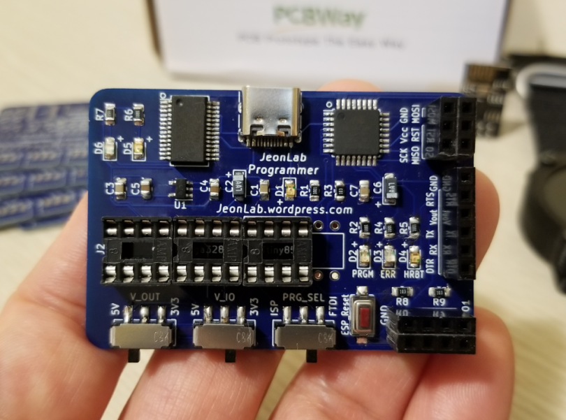
And assembled one.

Note that I assembled 3x 8pin DIP socket instead of 1x 28pin DIP socket. That’s because the last 4 pins for the ATmega328p are not used for programming and the SPI pins for the ATmega328p and the ATtiny85 are in the same order. See the schematic and you will get it. By using 8pin DIPs, it’s easy to place the ATtiny85.

For the ATmega328p chip, the V_out is set to 3V3 and the V_IO is set to 3V3, and the PRG_SEL switch is set to ISP. See the picture below.

For the ATtiny85v, the switch settings are the same as above.

Now for the ESP-01, the settings are: 3V3 for V_OUT, 3V3 for V_IO, and the PRG_SEL switch to FTDI.

The FTDI header is the same as the popular FTDI breakout board except for the CTS pin is replaced with the RTS pin. The CTS pin is not used for Arduino programming and the RTS pin is very useful for ESP programming which allows complext boot/reset button presses during uploads. Here is an example I use for the GPS watch 3.1 programming through FTDI output.

If you want to make one for yourself, you can order PCB directly from PCBWay.

Please leave comments if you have any questions or comments.

Thanks.

Sump pump monitor updated using ThingSpeak IoT

This post is an update from my earlier post about monitoring my sump pump activities. For more detail about the hardware configuration, please see that post.

As of May 30, 2022, Google has disabled the Less Secure Apps feature that uses Simple Mail Transfer Protocol (SMTP). So, I had to find a way to continue monitoring my sump pump activities and decided to use one of those IoT servers. I found there are many companies offered free account for individuals. My choice was ThingSpeak which I had heard of it before. Using their FREE account, you can send 3 million messages per year and the message update interval limit is every 15 seconds. Besides, each message and contain 8 data fields. That’s more than enough for me.

In Arduino IDE, you can install the library that is provided by ThingSpeak from the library manager. There are plenty of examples that you can use.

Here is the Arduino code that I modified for this project from an example code. Note that the header file ‘secrets.h’ contains your channel ID, API key and wifi credential. You will see it once you install the library and take a look at the examples.

/*
  WriteSingleField

  Description: Writes a value to a channel on ThingSpeak every 20 seconds.

  Hardware: ESP8266 based boards

  !!! IMPORTANT - Modify the secrets.h file for this project with your network connection and ThingSpeak channel details. !!!

  Note:
  - Requires ESP8266WiFi library and ESP8622 board add-on. See https://github.com/esp8266/Arduino for details.
  - Select the target hardware from the Tools->Board menu
  - This example is written for a network using WPA encryption. For WEP or WPA, change the WiFi.begin() call accordingly.

  ThingSpeak ( https://www.thingspeak.com ) is an analytic IoT platform service that allows you to aggregate, visualize, and
  analyze live data streams in the cloud. Visit https://www.thingspeak.com to sign up for a free account and create a channel.

  Documentation for the ThingSpeak Communication Library for Arduino is in the README.md folder where the library was installed.
  See https://www.mathworks.com/help/thingspeak/index.html for the full ThingSpeak documentation.

  For licensing information, see the accompanying license file.

  Copyright 2020, The MathWorks, Inc.
*/

#include <ESP8266WiFi.h>
#include "secrets.h"
#include "ThingSpeak.h" // always include thingspeak header file after other header files and custom macros

uint8_t connection_state = 0;
uint16_t reconnect_interval = 10000;
char ssid[] = SECRET_SSID;   // your network SSID (name)
char pass[] = SECRET_PASS;   // your network password
//int keyIndex = 0;            // your network key Index number (needed only for WEP)
WiFiClient  client;

unsigned long myChannelNumber = SECRET_CH_ID;
const char * myWriteAPIKey = SECRET_WRITE_APIKEY;

int sensorPin = 2; // from ATtiny85v detecting vibration
const long milsec_to_min = 60000;
int pumpIntervalMin;
unsigned long lastPumpOnMillis, startMillis;
int count = 0;
boolean trigger = false;

uint8_t WiFiConnect(const char* nSSID = nullptr, const char* nPassword = nullptr)
{
  static uint16_t attempt = 0;
  if (nSSID) {
    WiFi.begin(nSSID, nPassword);
  }
  uint8_t i = 0;
  while (WiFi.status() != WL_CONNECTED && i++ < 50)
  {
    delay(200);
  }
  ++attempt;
  if (i == 51) {
    if (attempt % 2 == 0)
      return false;
  }
  return true;
}

void Awaits()
{
  uint32_t ts = millis();
  while (!connection_state)
  {
    delay(50);
    if (millis() > (ts + reconnect_interval) && !connection_state) {
      connection_state = WiFiConnect();
      ts = millis();
    }
  }
}


void setup() {
  pinMode(sensorPin, INPUT);
  Serial.begin(115200);  // Initialize serial
  while (!Serial) {
    ; // wait for serial port to connect. Needed for Leonardo native USB port only
  }

  connection_state = WiFiConnect(ssid, pass);
  if (!connection_state) // if not connected to WIFI
    Awaits();          // constantly trying to connect
  else Serial.println("connected");

  //  WiFi.mode(WIFI_STA);
  ThingSpeak.begin(client);  // Initialize ThingSpeak
  int x = ThingSpeak.writeField(myChannelNumber, 1, 2, myWriteAPIKey);
  if (x == 200) {
    Serial.println("Channel update successful.");
  }
  else {
    Serial.println("Problem updating channel. HTTP error code " + String(x));
  }
}

void loop() {
  if (digitalRead(sensorPin) == HIGH) {
    if (!trigger) {
      startMillis = millis();
      trigger = true;
    }
    count++;
  }

  if (millis() - startMillis > 60000) {
    if (count > 100) {
      pumpIntervalMin = int((startMillis - lastPumpOnMillis) / milsec_to_min);
      lastPumpOnMillis = startMillis;

      ThingSpeak.setField(1, pumpIntervalMin);
      ThingSpeak.setField(2, count);
      //      int x = ThingSpeak.writeField(myChannelNumber, 1, pumpIntervalMin, myWriteAPIKey);
      int x = ThingSpeak.writeFields(myChannelNumber, myWriteAPIKey);
      if (x == 200) {
        Serial.println("Channel update successful.");
      }
      else {
        Serial.println("Problem updating channel. HTTP error code " + String(x));
      }
      delay(60000);
    }
    count = 0;
    trigger = false;
  }
  delay(10);
}

Leave a comment if you have any questions.

Thanks.

GPS Watch v3.1: ESP32 dual core FreeRTOS multi-tasking

ESP32 dual core

The ESP32 has two cores (2 Xtensa 32-bit LX6 microprocessors), core 0 and core 1. Those RF tasks, WiFi and Bluetooth, are normally run on the core 0 by default, and all the other tasks we program in Arduino IDE (or PlatformIO) run on the core 1. For my GPS Watch, since I don’t use WiFi or Bluetooth often, the core 0 is not used. What a waste! Well, I will explain later, but I do use WiFi for golf data (course coordinates and scores) transfer to and from my laptop or smartphone, but that happens only once in a while.

FreeRTOS

When you install the ESP32 core for Arduino IDE, it comes with the FreeRTOS library. FreeRTOS is basically task scheduler for microcontrollers. Not only you can schedule multiple tasks but also can define which core to use per task.

Multi-tasking

When you use a microcontroller without a task scheduler, it’s difficult to run multiple tasks. For example, you want to get the GPS data, to process the data, to display information on a display (LCD or any other target), and detecting user’s input such as switches. If each task takes very short period of time (say millisecond range), you can do these tasks in series. However, the GPS data read takes much longer time, hundreds of milliseconds or even longer if the signal is not strong enough. While the microcontroller is working on the GPS data processing, your switch input may not be detected properly. With my previous version, v2, I actually had to press the switch for longer period of time (a half second or so) to make sure the desired input is correctly registered.

As the ESP32 has the multi-tasking capability with the FreeRTOS and two cores, I could make it keep monitoring the switch status and GPS data reading (in GPS enabled modes like playing golf) on a separate core while all the other part (displaying date and time or processing GPS data for playing golf, etc.) on another core. Here is a summary.

  • core 0
    • continuous monitoring of left and right touch pad status
    • continuous GPS data reading from the GPS module in GPS enabled modes
  • core 1
    • sleep and wake up management
    • control different modes based on user selected menu (watch, golf, wifi file transfer, etc.)
    • display date/time and synchronize time to GPS RTC module for watch
    • calculate distances and count score for golf mode
    • working with SPIFFS memory to get the golf course data and store scores
    • show basic GPS data (to be upgraded for bike mode later)

FreeRTOS task scheduler set-up

You can find various examples online if you search for ESP32 FreeRTOS dual core programming, but here is a part of my code to show how to set up multi-tasks.

First, define the task handles.

TaskHandle_t Task_GPS_read = NULL;
TaskHandle_t Task_SW_L_monitor = NULL;
TaskHandle_t Task_SW_R_monitor = NULL;

Declare functions for the tasks. In Arduino, you don’t need to declare functions, but this is good to sort the functions as you want without seeing the annoying errors that your function is not declared in the scope just because of the orders of those functions in your code.

void Task_GPS_read_core0(void *pvParameters);
void Task_SW_L_monitor_core0(void *pvParameters);
void Task_SW_R_monitor_core0(void *pvParameters);

Functions.

void Task_GPS_read_core0(void *pvParameters)
{
  for (;;)
  {
    while (gpsPort.available() > 0)
      gps.encode(gpsPort.read());
    if (gps.date.isValid() && gps.time.isValid()) 
    {
      rtc.setTime(gps.time.second(), gps.time.minute(), gps.time.hour() + TimeZone, gps.date.day(), gps.date.month(), gps.date.year());
      rtc_updated = true;
    }
    vTaskDelay(200 / portTICK_PERIOD_MS); 
  }
}

void Task_SW_L_monitor_core0(void *pvParameters)
{
  unsigned long ms;
  for (;;)
  {
    if (touchRead(SW_L) < Threshold_L)
    {
      ms = millis();
      while (touchRead(SW_L) < Threshold_L)
        ;
      if (millis() - ms > 20)
      {
        SW_L_pressed = true;
      }
    }
    vTaskDelay(200 / portTICK_PERIOD_MS); // delay between tasks
  }
}

void Task_SW_R_monitor_core0(void *pvParameters)
{
  unsigned long ms;
  for (;;)
  {
    if (touchRead(SW_R) < Threshold_R)
    {
      ms = millis();
      while (touchRead(SW_R) < Threshold_R)
        ;
      if (millis() - ms > 20)
      {
        SW_R_pressed = true;
      }
    }
    vTaskDelay(200 / portTICK_PERIOD_MS); // delay between tasks
  }
}

Finally, in the setup(),

  xTaskCreatePinnedToCore(
      Task_GPS_read_core0, /* Task function. */
      "Task_GPS_read",     /* name of task. */
      4096,                /* Stack size of task */
      NULL,                /* parameter of the task */
      1,                   /* priority of the task */
      &Task_GPS_read,      /* Task handle */
      0);                  /* pin task to core 0 */

  xTaskCreatePinnedToCore(
      Task_SW_L_monitor_core0, /* Task function. */
      "Task_SW_L_monitor",     /* name of task. */
      4096,                    /* Stack size of task */
      NULL,                    /* parameter of the task */
      1,                       /* priority of the task */
      &Task_SW_L_monitor,      /* Task handle */
      0);                      /* pin task to core 0 */

  xTaskCreatePinnedToCore(
      Task_SW_R_monitor_core0, /* Task function. */
      "Task_SW_R_monitor",     /* name of task. */
      4096,                    /* Stack size of task */
      NULL,                    /* parameter of the task */
      1,                       /* priority of the task */
      &Task_SW_R_monitor,      /* Task handle */
      0);                      /* pin task to core 0 */

To determine the stack size, at the end of the setup(), add these lines and see how much stack is NOT used. And then give some more to avoid any stack-overflow.

  Serial.println(uxTaskGetStackHighWaterMark(Task_GPS_read));
  Serial.println(uxTaskGetStackHighWaterMark(Task_SW_L_monitor));
  Serial.println(uxTaskGetStackHighWaterMark(Task_SW_R_monitor));

Once you determine the stack sizes, you can remove these lines or comment out.

GPS Watch v3.1: Watch

ESP32 has a real-time clock (RTC) with an external crystal, but it’s accuracy is not really good enough for a watch. In my tests, the clock showed more than one minute of error after a few hours which means there will be several minutes of inaccuracy after one day.

I was thinking to add a separate RTC module such as DS3231 with a crystal, but those components will take up precious estate on the PCB. Another thought was to compensate the error every minute or hour, but the error depends on the environment temperature and the calibration is not simple during the sleep modes.

I haven’t posted any article on my previous version, v2 with ATmega328p (no RTC), but I used the GPS module (uBlox, CAM-M8C) to synchronize the clock. The GPS module has a built-in RTC module and it synchronize the time and date whenever the GPS module is fixed and it keeps running as long as the back-up battery is connected, and its accuracy is pretty good. In my experience, I haven’t noticed more than a couple of seconds of error for a few months without GPS fixes during the winter, off-season.

The GPS module I used for this version, v3.1, is Quectel L96-M33 and this module also has the built-in RTC module. I used to have the watch to synchronize the time to the GPS module whenever I turn on the watch for v2, but it takes time (turn on the GPS module, patch the NMEA message, get the time and date data, and synchronize the internal RTC time) which is usually a little less than 2 seconds. So, there is a delay to show the time when I click (or touch) the switch.

In order for longer battery life, the ESP32 is in light sleep mode most of the time. There are a few different sources that can be used to wake it up such as touch-pad, timer, GPIO, external IO. I have enabled two sources, the touch-pad and the timer. Using the timer, the watch wakes up every 3600 seconds (1 hour) and synchronize time to the GPS RTC. This way I could keep the accuracy within a minute all the time and the watch immediately show current time without any delay when I touch the pad. During that 1 hour between synchronizations, there is still some error, but it’s not accumulate. At least once in an hour, it’s corrected.

GPS Watch v3.1: Hardware assembly

I designed a PCB using KiCad and ordered 3 prototype boards (0.8mm thick, 2oz copper) from OSHPark.com. The front and bottom of the PCB look like these.

As you can see on the left edge of the front layer, my initial plan was to add a GPS antenna printed on the PCB. It works fine if the LCD is not attached at the back side of the PCB, but with the LCD, which has metal cover at the back of the screen, the antenna doesn’t work properly. I’m going to show the modified antenna in this post.

Some of you may have noticed there is no switch although there are silkscreen letters, SW_R and L, but they are just round test point pads. I’m going to cover this part in this post as well.

Here are a couple of pictures after assembly.

During the assembly, I found a couple of pins on the ESP32 didn’t work as they were expected. It turned out that some pins for touch pad are one of those strapping pins (special functions for ESP32, especially for boot) and some pins behave differently from what I had anticipated. Anyhow, I had to move a couple of pins to another available pins. That’s why there are a few green 30 gauge wires between the ESP32 and the GPS module (L96-M33). Oh, the metal cover on the ESP32 fell off while I was attaching the module and I thought I didn’t need it since I don’t use RF module (for wifi or bluetooth) much for this watch. It actually saved some space between the PCB and the battery, so I could add a thin SMD piezo buzzer (9mm x 9mm x 1.8mm) as shown in the 3rd picture above (red arrow). A ceramic 0.1uF capacitor (yellow arrow) is also added to the buzzer pin to prevent unwanted buzzing noise sometimes.

GPS antenna

I have done some experiments with a few different GPS modules (ublox, Quectel, PA6C, M-1000) with different shape antennas and found it’s not necessarily to be big or certain shape. Maybe for some purposes, you need specially designed antennas, but for my projects, as long as it can fix the GPS data, I don’t really care about other features. So, any copper (to solder) tape (or foil or sheet) with a short wire connected to the RF-in pin on the GPS module works perfectly fine. I tried various sizes (20-40mm by 3-10mm) but didn’t see too much difference. Only thing you need to be careful is not to put the antenna strip too close (less than a couple of mm) to any ground plane (PCB or back side of LCD, etc.) The antenna strip is shown in pictures above. In the 3D printed lower case of the watch, there is a slot for the antenna.

Touch pad switches

A watch (or any portable devices) needs switches to interact with a user. In most cases, I found 2 switches are good enough. One of the good features of the ESP32 is that it has built-in capacitive touch pad pins and I wanted to try these pads as switches. There are some settings to set properly in order to use them consistently and I will explain this part in another post with the program.

To assemble the watch, I used 4 tapping screws and my idea was to use 2 of them as switches. It took some time to find proper way to get the touch input and settings, but it works pretty good. From the PCB, I soldered two short braided wire that go into the screw hole so that the screws contacts the wire and make the screws as touch pads.

Without the cover plate, the assembled watch looks like this.

Introduction to GPS Watch v3.1

Introduction

This post is to introduce my new version of a GPS watch, JeonLab GPS Watch, v3.1. It took some time to design, order/wait parts, assemble, revise/correct design, write codes, and debug program, but finally (not necessarily mean all done), I can show something now. Since I can only work on my personal projects for my spare time after work or over the weekends, the progress is very slow, but that’s the fun part of this hobby, making things.

Well, I have mentioned before in a few posts ago that I have thought about making a new version of the GPS watch for golfing. I have collected possible combinations of a microcontroller (faster than ATmega328p with bigger memory), a GPS module (smaller the better), and a display. I also posted a few to show some of my trials including the Lilygo e-paper watch and the Sharp memory LCD.

Regarding the display, as in my post for the e-paper display, the e-paper display cannot be used outdoor under UV. The Sharp memory LCD has poor contrast and is too small. I have kept searching for a good display and found a round IPS LCD (1.28″ diameter, driver: GC9A01) and thought this might be a good display for a watch. I have experienced with another IPS LCD and satisfied with it’s visibility, current consumption, and control. And I decided to use an ESP32 for my microcontroller (MCU) and TTGO T-Micro32 was the smallest module I could find. Now for the GPS module, I bought a Quectel L96-M33 module which is the same size as u-blox CAM-M8 (that I have used for the previous version, v2), but cheaper.

It was my first time to program ESP32 for my complete project and found the ESP32 is quite different from my longtime favorite ones, ATmega328p or ATtiny85v. Since I assembled the watch and started tests and program coding, there were quite number of challenging issues to figure out. At some point, I was very close to give up and toss it in the garbage can, but kept trying to find root causes and resolved those issues. There is always a way. Never give up! I have learned a lot about this particular MCU and programming.

The hardware is done and, for the programming, I have finished the watch part and showing GPS data, but not the play golf part yet. So, for the next few (or more) posts will cover the detail of the design and tips & tricks I have learned.

Specification

Here is a bill of material of major components.

  • MCU: TTGO T-Micro32 (ESP32-PICO-D4, 4Mb flash)
  • GPS: Quectel L96-M33
  • LCD: 1.28″ round IPS (driver: GC9A01)
  • 3.3V LDO: AP2112
  • Battery: 450mAh round LiPo, 35mm diameter, 4mm thick
  • LiPo battery charger: MAX1555
  • Programming and battery charge port: USB type-C receptacle
  • Buzzer: SMD piezo, 9mm x 9mm x 1.8mm
  • Case: 3D printed
  • Wrist strap: 24mm nylon

Programming environment and libraries:

  • Computer OS: Linux Mint 20.3, Xfce 64-bit
  • Visual Studio Code
  • PlatformIO for Arduino
  • Arduino IDE 1.8.19
  • Libraries

Main functions:

  • Watch
    • Time and date synchronized to GPS real-time clock (RTC)
    • Show time and date
    • Show battery level
  • Show GPS data
    • UTC time and date
    • Coordinate
    • Number of satellites fixed
    • hdop
    • Heading angle
    • Altitude
    • Ground speed
    • Battery level
  • Play golf (based on previous version, v2. Not implemented yet as of writing)
    • Course data needs to be stored in the SPIFFS memory manually
    • Automatic selection of the course (nearest)
    • Count the number of shots (manual entering by clicking a switch) of current hole and total
    • Show the distance (in yard) to the green
    • Show the distance (in yard) from the last shot
    • Show current hole number and par
    • Show time and battery level
    • Save number of shots per hole and date/time and course name in the SPIFFS memory (thinking to send this data over Wifi upon request from my phone or laptop)

Schematic

JeonLab GPS Watch v3.1 schematic

Pictures

Here are some pictures.

As mentioned above, for the next series of posts will cover the detail of the design and the program.

Quectel GPS module set-up tips

Probably you have seen one of those Quectel GPS modules working with Arduino. I have two of them, L96-M33 that I have bought for a GPS watch project and LG77L which is included in the GPS version of the LilyGO e-paper watch module.

In their Protocol Specification documents, you can find all the available commands to set up or control the module for your projects. Note that depending on what module you are using, not all the commands are available, but for those modules I have pretty similar sets of commands are used and I wanted to share some key commands here for those who are using these modules.

Back-up mode

The back-up mode is useful to save power for a portable device with batteries. In order to go into back-up mode by software, you need to pull the wakeup pin low first. Then send a command “$PMTK225,4*2F” via the serial port you opened for the GPS module. It looks like this in Arduino sketch.

digitalWrite(GPS_WAKEUP, LOW);
gpsPort.println("$PMTK225,4*2F"); // GPS backup mode

To wake the GPS module up, simply pull the wakeup pin high.

digitalWrite(GPS_WAKEUP, HIGH);

Stand-by mode

The stand-by mode draws a little bit more current than the back-up mode, but still draws much lower current than the continuous mode and can fix quickly. For the stand-by mode, you don’t need to pull the wakeup pin low. Just send this command.

gpsPort.println("$PMTK161,0*28"); // stand by mode

To go back to the continuous mode, send a single byte (any character). Here is an example.

gpsPort.println("a"); // "a" can be any character

Note that you need to wait at least 120ms before waking up the GPS from the stand-by mode.

Baud rate change

The default baud rate is 9600 bps, but you can change it to higher rate with PQBAUD command. Here are some example. For other baud rates, change the value and get the right checksum. To calculate the checksum, there are websites that calculates it for you. Here is a link that I’m using.

gpsPort.println("$PQBAUD,W,115200*43"); // set baud rate to 115200 bps
gpsPort.println("$PQBAUD,W,9600*4B"); // set baud rate to 9600 bps

Update rate change

The default update rate is 1Hz, but you can change it up to 10Hz. Here are a couple of example.

gpsPort.println("$PMTK220,100*2F"); // set position fix interval to 100ms (10Hz)
gpsPort.println("$PMTK220,200*2C"); // set position fix interval to 200ms (5Hz)
gpsPort.println("$PMTK220,1000*1F"); // 1Hz

Note that you will need faster baud rate for higher frequency, obviously.

Sharp memory LCD review

As I mentioned in my previous post, the e-paper displays have a problem under UV light. So I wanted to try another display and found Sharp memory LCD which draws very low current and is supposed to provide good contrast under ambient light. It’s not transparent, so backlight doesn’t work.

I bought a 1.26 inch LS013B7DH05 from Aliexpress and tested with a test sketch included in the Adafruit_SharpMem library. I was expecting to see brilliant contrast images and texts, but the result was quite disappointing. See below pictures. Only when the illuminated angle of the light source is the same as your viewing angle, you can see good contrast. In other words, the viewing angle is very limited. I tested outdoor as well and the result was not improved. As you can see, as you tilt the display, it gets dark quickly.

If you rotate the screen 90 degrees either CW or CCW, the viewing angle gets even narrower. Not good.

It requires 3kbytes of buffer, so ATmega328 based Arduino cannot drive this display. I used ESP32 and found another downside of this display. At high CPU frequency (default frequency of the ESP32 is 240MHz), say about 40MHz, the display shows noises. In my experiments, only at 10 and 20 MHz, it works fine. See below pictures.

There are many other models which may be better than this model. Actually there are many websites that introduce these memory LCDs as good display. Another downside of these LCDs is the price. It’s quite expensive, so I don’t want to buy another model and try.

So, I have resumed my research on finding a (simple) way to block the UV for the e-paper display. Any idea?

E-paper display problem under the sunlight

I already knew the e-paper (or e-ink) displays were not suitable under sunlight. So for those outdoor products, I think they attach protective a film that can block the UV light. Even on a cloudy day, there is still significant amount of UV light outdoor.

So, my plan was to attach a UV-stabilized acrylic sheet. However, it turned out that’s not enough. See below picture.

The black text got faded and it’s difficult to read. Disappointed.

I have ordered a screen protector film that was advertised as it can block 99% of UV light and still waiting for it. Unless it can actually block the UV light properly, I will need to find another solution for the display.